This article originally appeared in Orbital Debris Quarterly News, Volume 19, Issue 2, April 2015.
J. HYDE, E. CHRISTIANSEN AND D. LEAR
The Orion EFT-1 mission launched from Cape Canaveral on 05 December 2014 and ended nearly 4.5 hours later with a successful recovery in the Pacific Ocean off of San Diego. As shown in Fig. 1, the first orbit had an apogee altitude of 890 km and a perigee of 200 km. The second orbit reached an apogee of 5,808 km. NASA civil servants and contractors from the Hypervelocity Impact Technology (HVIT) Group at the Johnson Space Center as well as Lockheed Martin personnel from Denver performed postflight inspections for micrometeoroid and orbital debris (MMOD) damage on the EFT-1 capsule at the Naval Base San Diego Mole Pier and the Launch Abort System Facility at the Kennedy Space Center. The Orion capsule was recovered in good shape, but the forward bay cover (jettisoned during the main parachute deployment) sank before it could be recovered. Capsule areas that were examined during the inspection campaign include the back shell thermal protection system tiles, back shell thermal barriers, reaction control system thruster nozzles, base heat shield acreage, docking hatch thermal protection system blankets, docking hatch window, and crew module windows.
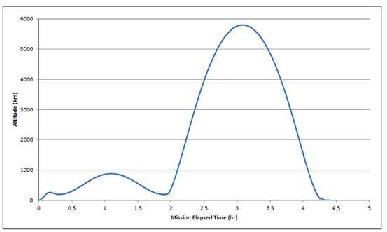
Figure 1. EFT-1 altitude versus mission time.
In general, the postflight MMOD inspection process can be divided into four tasks:
- Survey: initial screening for defects and anomalies
- Characterization: examination for distinctive hypervelocity impact (HVI) features
- Documentation: location and feature sizes of HVI defects are measured and recorded
- Analysis: detailed investigation to discern details of impact source.
The first two activities are performed in the field while the documentation task can include both field and lab work. We have completed the field work and are now involved in the lab work. Specifically, we are now conducting non-destructive evaluation (NDE) of the suspected MMOD impact features using X-ray computed tomography (CT) and optical microscopy. After the NDE work, a scanning electron microscope with energy-dispersive X-ray spectroscopy (SEM/EDX) will be used to characterize the elemental composition of HVI impactor residue.

Table 1. EFT-1 Postflight MMOD Inspection Preliminary Findings, TPS
Initial surveys and characterizations produced 25 regions of interest (ROI) on backshell thermal protection system tiles. An internal imagery review and additional inspections reduced the ROI list down to six features that were designated as “possible MMOD.” Table 1 provides details of the six potential impact sites in the TPS tiles. Figures 2 and 3 provide general locations of the six regions of interest on the capsule TPS. Figures 4 and 5 show typical imagery acquired during inspection work in the field. Five of the six tiles containing the potential MMOD damage were removed and sent to the HVIT group at JSC for additional analysis with higher magnification microscopes and 2D/3D surface profilers. A typical microscope image and 2D crater profile from the lab can be seen in Fig. 6.
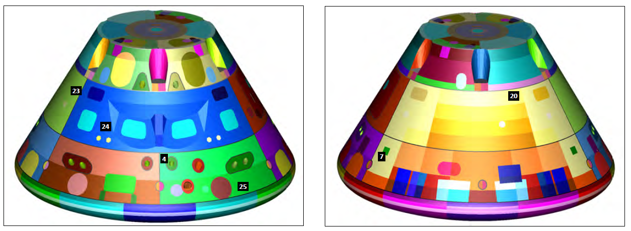
Figure 2. EFT-1 postflight MMOD inspection preliminary findings, backshell TPS: 0° view. Figure 3. EFT-1 postflight MMOD inspection preliminary findings, backshell TPS: 180° view.
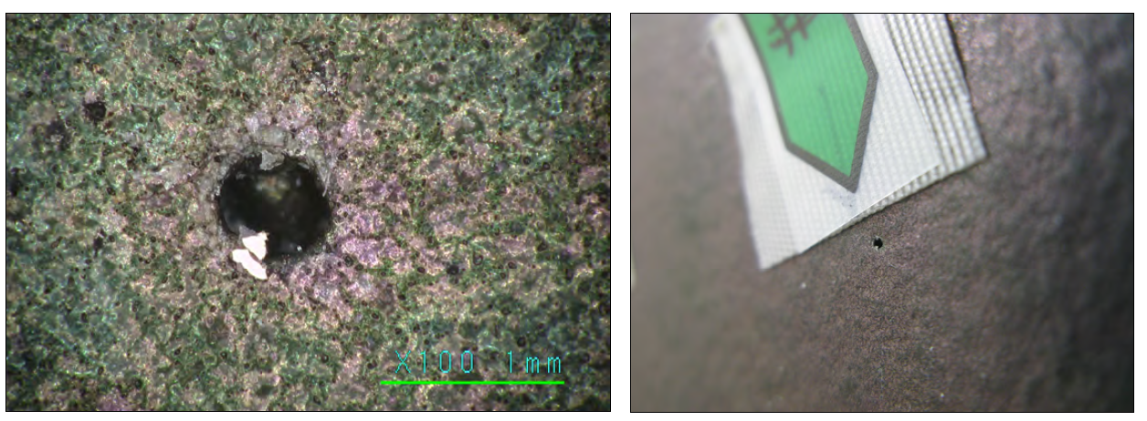
Figure 4. Field imagery of ROI #20, feature size = 0.63 x 0.56 mm, depth = 0.54 mm. Figure 5. Field imagery of typical region of interest (ROI #20).
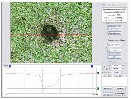
Figure 6. Laboratory measurement region of interest #20.
Four crew module windows and the hatch window were also examined for MMOD damage features. A total of 42 small window features were found; 27 on the crew module windows and 15 on the hatch window. It is very possible these small features were due to a non-MMOD source, but the investigation into the cause of these damages is ongoing. Figure 7 provides the total number of observations for each window. The damage features in the windows (see Fig. 8) were all fairly consistent in appearance and ranged from 0.1 mm diameter to 0.5 mm diameter.
An as-flown analysis was performed by Lockheed Martin against the final trajectory using the Bumper 3 code and the ORDEM 3 orbital debris environment. Figure 9 shows the observed TPS tile damage (in this case depth was used) with the results of the Bumper code predictions for ORDEM 3 (including MEM-R2). Preliminary results indicate that more damage was observed than predicted by the as-flown assessment. A similar assessment was performed for window damage based on internal fracture diameter and ORDEM 3 predicted 0.2 features of 0.3 mm and greater diameter. Assessment work is still underway.
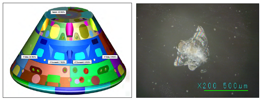
Figure 7. EFT-1 postflight MMOD inspection results, crew module and hatch windows. Figure 8. Typical crew module window impact of ROI #19 (+Y forward). Internal fracture dimensions = 0.51 x 0.41 mm diameter, crater dimensions = 0.36 x 0.18 mm diameter, depth = 0.03 mm.
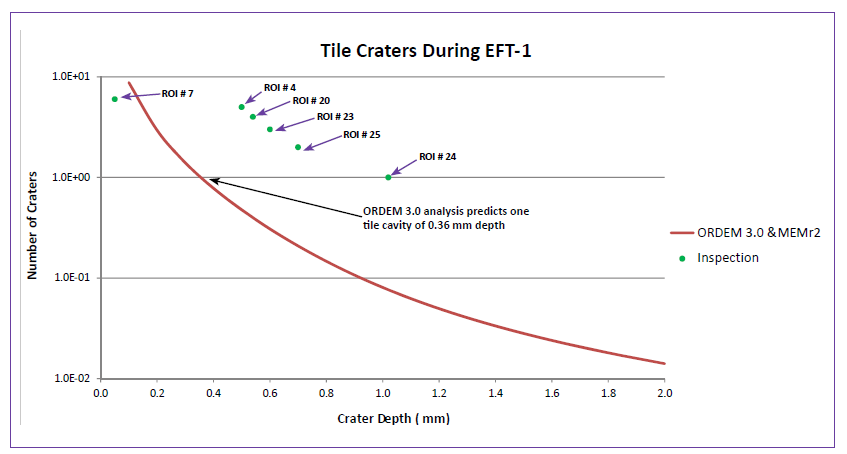
Figure 9. As flown prediction for tile crater depth compared to observations.